

 View Cart
 Search Our Site
 Products
 Knowledgebase
 Company Info
 Contact Us
 Help
HelpLoop Current & Circuit Loss Technical Bulletin
Loop Current is the amount of electrical energy flowing through the telephone and line, as opposed to the voltage which is the force behind the energy. There is a definite correlation between the Loop Current and Line Voltage (Ohm's Law), but the loop current reading is often what indicates the problems in telephony... not the voltage reading. The carbon transmitter used in telephones has been the controlling factor for years, since it needs over 20ma to sound good.
THE PROBLEM:
I was made aware of the high loop current problem by Don Jordan of Newmont Gold Co. in Las Vegas, NV (a long-time phone man), a number of years ago. I didn't have a clue what was causing these problems before that, but as soon as he explained it to me it was like a light bulb lit up, and I started remembering all of the weird cases that I couldn't fix that were probably loop current problems.
Until about the mid 1980's, the big problem with loop current was that it was often too low. That was when the only way to get from point A to point B was a pair of copper wires. Now, with the proliferation of electronic Central Offices and electronic pair gain equipment: T1, Fiber Optics, Remote Central Offices and SLICs in every suburban and even rural area (you can see these Huts and Buried Vaults scattered around everywhere), over 90% of the problems are high loop current. This is because the manufacturers of the "far end" pair gain equipment have adhered to a very old specification for loop current, but one that is still valid, that says between 23ma and 120ma are OK - but the CPE is much closer to the source of the talk battery than the old days. When the phone company tells you that they are within specs (while smoke wafts off your trunk cards at 80ma of loop current), they're right!
Both the phone company and CO equipment manufacturers have no incentive to bring the loop current down. All they have to do is make a standard 2500 set work (which has no active electronic circuitry to burn up), and the farther out it works... the better. Until the FCC sets a new standard for high loop current (unlikely), or CPE manufacturers take account of the high loop current problem (seems unlikely), the Interconnect company will be left holding the repair bag for these problems. Most CPE equipment was designed based on low loop current problems... it works well right down to 23ma. CPE manufacturers have been really slow to try to head off the high loop current problem. In the rare case of low loop current (below 23ma), the phone company is required to bring it up to 23ma.
The main problem created by high loop current is heat. The components on the trunk card or telephone that connect to a CO line with high loop current get hotter than the manufacturers planned for. When the components get hot, their specs change, which makes the circuit work differently - usually with unpredictable results. If the loop current is high enough, a component can get fried, and the device will stop working instead of just having problems. Eventually, the heat from the high loop current can damage one or more components on a trunk card, shortening the life of the card.
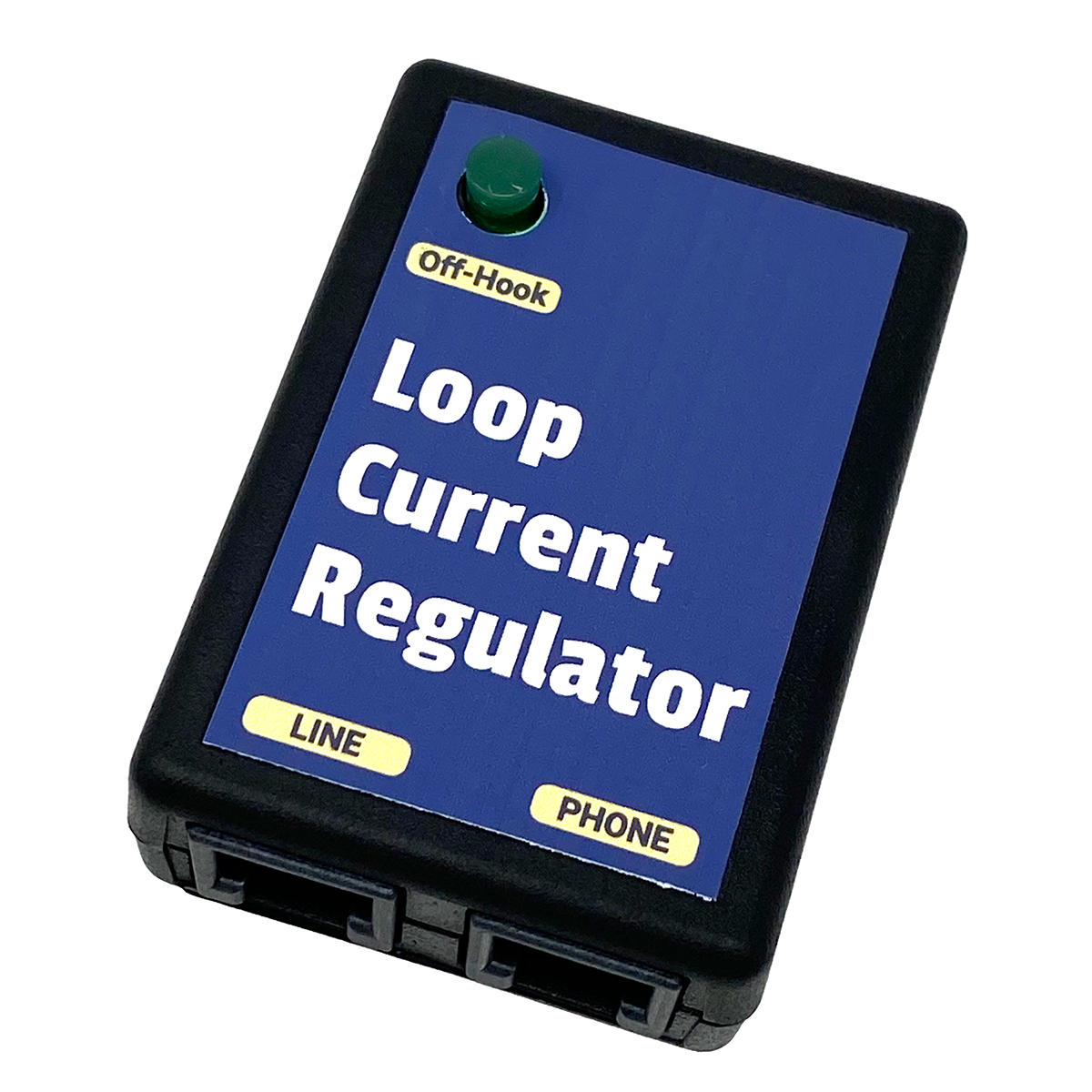
If your Loop Current is high, our Loop Current Regulator #WAL5S can bring it down to the proper level, protecting your equipment.
In some cases, you may have a problem with low loop current on an analog station port or phone line. We have a Loop Current Booster™ #KIT8L , which will bring the loop current up to 27ma, and also add 24VDC to the on-hook talk battery (24V talk battery would be 48V talk battery).
We also have the Ring Voltage Booster II™ #KIT8R , which will add 7.5 REN of 20-cycle ringing at 90VAC RMS to a phone line or analog station port. It passes Caller ID, message waiting and CPC signals. The combination of the Loop Current Booster™ and Ring Voltage Booster™ do the same thing as the old Proctor Long Loop Adapter 46222 (which is no longer manufactured). These Boosters are separate items, so they can be purchased separately if you only need to cure one problem (ringing or loop current / talk battery).
Keep in mind that neither of these units will bring up the volume of a phone line or OPX. For that, you'd need a 2-wire amplifier (see the Telephone Line Audio Level Primer at the end of this bulletin).
BACKGROUND:
Phone wire used to be much bigger than the 24-gauge standard today, so they could carry current the long distances that needed to be traveled from the CO (Central Office). There is a definite loss of electrical energy per foot of copper wire. The closer the CO got to the subscriber's location (because there are more and more COs these days), the less there was need for the current carrying capability of the bigger wires. Since the 1960's, phone wires have gotten smaller, except in rural areas where the distance to the subscriber still requires the bigger wires with larger current carrying (and lower circuit loss) capabilities. Keep in mind that some very rural COs operate on their own totally different voltages and currents to get the phone service to their subscribers (like 100VDC talk battery).
At the end of a long loop, the current that left the CO at 35ma might be 18ma because of wire loss (resistance), and the audio level may be well below -8.5db, causing it to be hard to hear. The circuit loss (volume) can be given a boost by the phone company by putting load coils into the loop, usually on loops over 3 miles.
Glenn Witherspoon, a retired phone man in North Huntington PA, called with an explanation of how he would determine whether to install load coils when he was with the Phone Company. He said they would never put load coils in the loop if it was less than 15,000 feet to the premise, in which case they would install three load coils (they wouldn't install just one). The first would go at 3,000 feet, the next at 9,000, and the next at 15,000 feet.
I've also been told that depending on the value of the load coil (they come in different inductance values), the last load coil should be at least a couple of thousand feet from the premise.
The load coil uses inductance to increase the audio voltage (sound level) at voice frequencies, while rolling off higher frequencies. If you need to use the higher frequency capabilities of the phone line for high-speed data (like a 56K modem or DSL), you may have to get the load coil removed to allow those higher frequencies to pass through (although the voice capabilities of the line may then be unusable due to the distance). Data circuits have always been adjusted 13 dB below voice levels (they like lines with low volume).
In some cases, the Phone Company screws up and there's a misplaced load coil on the pair, either too close to the premise, too close to the CO, or not needed at all. Although everything is computerized, a lot of the plant records indicating which pairs have had load coils put on them in the past are incorrect. That means that when someone gives up a line that needed a load coil, and the pair is re-used, the Phone Company might not know the load coil is on that pair, and it could create a problem on the new phone line that pair is used for. Mis-placed load coils will change the impedance of the line and could even make it too loud, which can distort both voice and DTMF digits (causing voicemail DTMF recognition problems).
A special TDR (Time Domain Reflectometer) can see the load coils on a phone line and pinpoint the exact number of feet from the premise. If you're having strange problems, especially with DTMF recognition, it's not a bad idea to ask the phone company to check the line for mis-placed load coils. Most TDRs can see out to the first load coil on a line. A special TDR (more expensive) can see out to 5 or more load coils.
Phones Companies use another piece of equipment that causes strange problems... Pair Gain Equipment. Phone companies today have little or no interest in putting more copper in the ground. If a premise has a six pair going to it from the nearest pedestal, and the subscriber needs seven lines, the Phone Company has two choices, bury more copper cable, or use an electronic gizmo to get two lines from one of the existing pairs.
A voice T1 is simply pair gain equipment, getting 24 lines from one or two pairs of copper. A T1 is expensive because the signal needs to be repeated every 6,000 feet. In the case of a lack of facilities (copper) to a particular building, the copper pairs usually aren't going very far from the pedestal or pole to the premise, and they usually don't need to very many lines, so some fairly inexpensive electronics can split a single pair of copper into two or more lines.
The problem with pair gain equipment is that it sometimes does a crummy job of emulating a real phone line. This stems from the old telephone company philosophy (excuse) that they will only guarantee that a line works with a regular 2500 set, and a 9600 baud modem. The reality of the world is that there are almost no 2500 sets connected to any Phone Company's lines, and almost nobody that wants their modem to connect at a slow 9600 baud. But they don't care. They don't have to. It's your job to make your system work with whatever lines they provide.
Some pair gain systems are known for putting out noise (common mode noise that you can't hear, but that's fixed with our Modem Filter™), having problems with Caller ID, or various other problems - especially with high speed data (they usually won't pass anything over 24K). Reading the loop current and voltages on the line might point out where the problems are. In some cases, you may be able to get the phone company to switch the pair gain equipment to a different set of lines, if your customer is using a particular line for a special application (like a fax, modem, etc.). The Phone Company won't tell you that they're going to put pair gain on a line. You find out when there are problems, usually after adding a new line, and the readings you take on a couple of lines look different than the other lines.
The Phone Company may put pair gain on one or more lines without telling the subscriber, and with no new orders for the subscriber. There may be a new tenant moving into the building, and they're out of pairs, so they put the pair gain equipment on an existing tenant's pairs in order to give service to the new tenant. You have absolutely no control over that and can't complain about it. The Phone Company can do whatever they want to get dial tone to the NI.
CLECs make it very difficult to get problems resolved on telephone lines. They often use the LEC's copper, so they have little or no control over what happens, and often won't offer the same level of service as the LEC. Most won't offer a trunk, which is conditioned better than a line, and can fix strange problems (see the Primer on Telephone Line Audio, below).
UNFIXABLE DATA PROBLEMS:
Generally speaking, loop current above 27ma will cause problems ranging from intermittent garbage to "no connect" on modems. It's going to be different in every case, so you have to keep loop current in mind as a possibility when you have a problem. I've been able to fix some of these problems by using a different brand modem, but it's not convenient to carry around a box of modems for testing. A customer called me about a location with an AT&T System 75 switch with single line stations, where the users were having trouble connecting or getting garbled data intermittently with laptop computers and modems connected to the single line station ports. The loop current wasn't super high, I think it was in the 35 to 40ma range, but the installation of Loop Current Attenuators at the frame for those stations using laptops solved the data problems by reducing the loop current below 27ma. Loop current problems are not limited to CO lines. They also can occur on PBX or Key System single line station ports and Analog Telephone Adapter (ATA) ports.
Since fax transmissions are just high-speed data, it's common for high loop current to cause problems with fax machines.
Keep in mind that some station ports are 24VDC, instead of the normal 48-50VDC voltage of a CO line. The same loop current specifications apply to the lower voltage... between 23 and 35ma. The dip switch settings on our Loop Current Attenuator #WAL1T are sometimes too "coarse" at the lower voltage (loop current would jump from 22 to 29ma). Our Loop Current Regulator™ #WAL5S , which automatically keeps the loop current at 25ma, should work fine on a 24V line.
COMMON SYMPTOMS OF HIGH LOOP CURRENT:
Most phone systems work OK with loop current in the 23 to 35ma range, although there are some that will cause problems above 27ma. One that comes to mind is the Walker Poet. One of our customers reported that he had intermittent crosstalk, even after replacing everything - KSU, cards and power supply. Walker tech support suggested that he check the loop current, which was found to be 32ma, normal in most cases. Walker said to get the current down to 27ma or less, and the problem was cured. In one case on another type of phone system, crosstalk was repaired by replacing the trunk cards, but the problem kept reappearing. Constant high current would eventually break down (damage) the components on the trunk card, and crosstalk would return.
There have been numerous reports of memory failures in equipment like dialers, faxes and answering machines.
I've had quite a few reports of Panasonic 2-line phones getting damaged by loop current over 40ma. It usually effects just one line on one phone first, but you will eventually replace all of the phones.
Many CO line (Trunk) cards are burned up on all types of systems every day... some under maintenance and some billable. In some areas, the loop current is running in the 80 to 105ma range. At that point there's no way you can make money with a maintenance contract without a Loop Current Regulator on every line!
If you're going to be installing a T1 Channel Bank, verify that the loop current is down at a reasonable level before committing to it, or you could burn up the trunk cards in your phone system. Most modern Channel Banks have reasonable loop current, but it's worth checking to prevent problems later.
I've had a number of calls from Long Distance dialer providers whose dialers had all kinds of strange problems with high loop current. Likewise, the payphone industry seems to be hit hard due to the sophisticated electronics in their phones, and the high-speed modems they use to transmit call detail data.
Symptoms of High Loop Current Include:
Burned Out Key, PBX or Data Equipment
Garbled Data and Modem Failures
Cut-offs & Squealing on Lines
Crosstalk, Echo & Hollow Sounding Lines
Numerous Intermittent Circuit Failures
Off Premise Equipment Problems
Symptoms of Low Loop Current:
Poor Voice Transmission Quality & Low Volume
Ghost Rings
Wrong Numbers
Lost Calls During Transfer
Data Loss
High or low loop current may affect Caller ID, but the #1 reason for Caller ID problems is high AC induced on the line (see our Longitudinal Imbalance Tech Bulletin), greater than .5VAC from tip to ground or ring to ground.
Considering the problems that loop current can cause, if you have weird unexplained problems, you should probably go right out and take a reading on the lines... it's easy! Dave Williams of Frontier Communications in Belgrade, MT says he is checking the loop current on the CO lines on every system he installs, which will head off customer disputes. It's not cheap to bring down the loop current in many cases, the main dispute being who pays for the repair (everybody points at the phone company first, but your finger will fall off before you get them to pay for it!). If there is low loop current, below 23ma, the phone company is responsible for getting it up to 23. I've talked to guys in rural areas who said that the phone company told them they just couldn't get it up to 23ma. You may have some recourse through your state's Commerce Commission, but who has the time for that? We do sell a Loop Current Booster™ #KIT8L .
MEASURING LOOP CURRENT
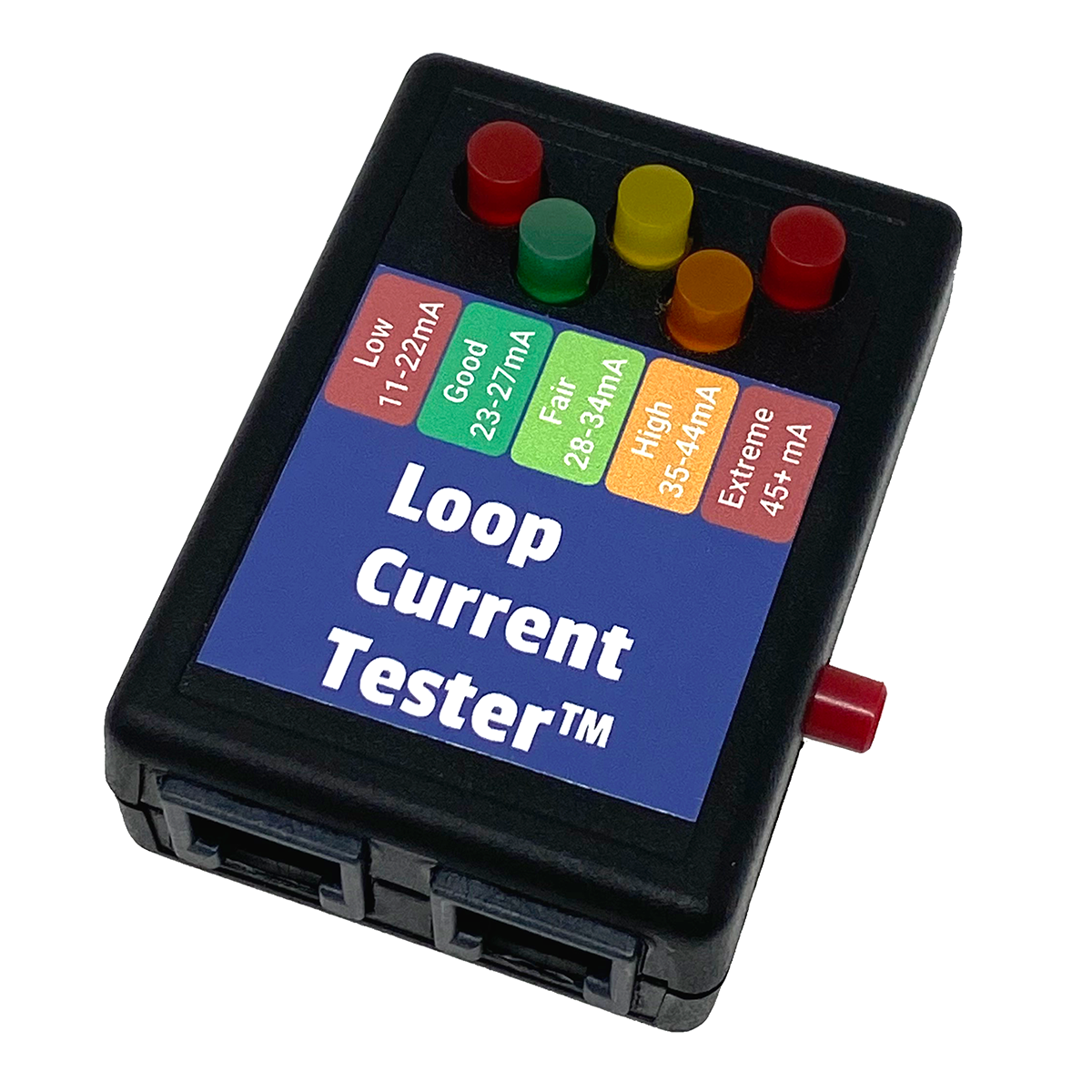
Measuring the loop current is easy. Our Loop Current Tester™ #TOH7O is the easiest way to test. Just plug it into a modular jack on the line (not in-series), push the button, and read the loop current off the LEDs.
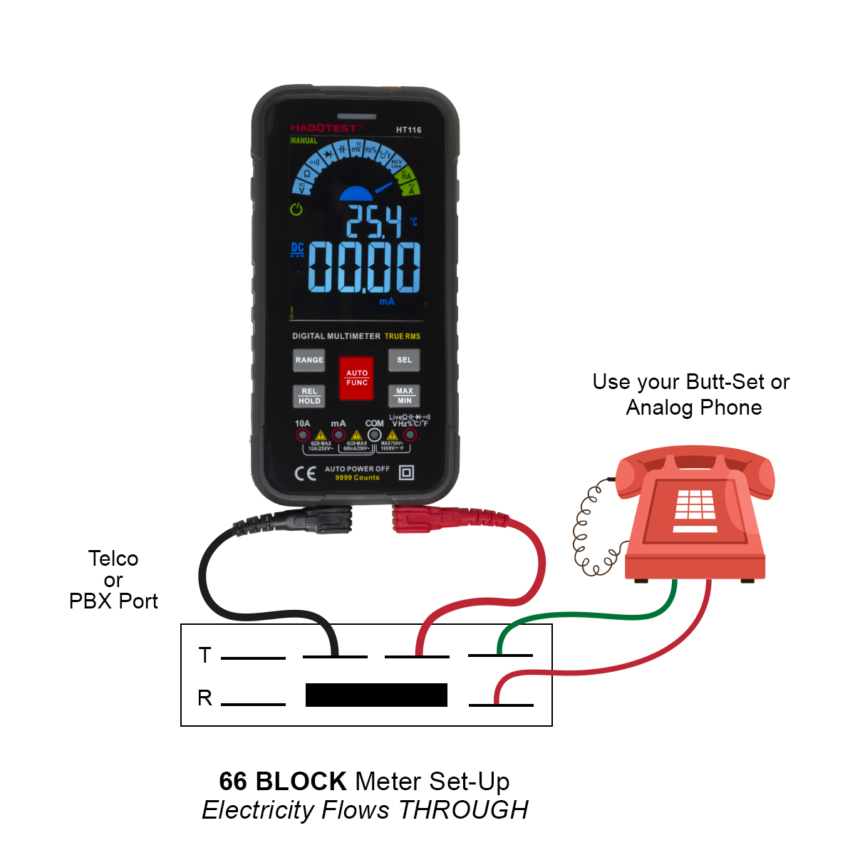
Otherwise, you can use a good quality DIGITAL volt-ohmmeter with a DC milliamp scale. An analog meter, except one designed for telephone work, will usually not give you accurate readings. A Fluke, or a few of the Radio Shack meters will do OK - within a couple of ma. The connection diagram for a meter (above) shows the meter in-series with the telephone instrument or system. That will give you the most accurate reading with a meter, since it's going through a 600-ohm or 900-ohm instrument (or Butt-set).
As an alternative to connecting the meter in-series with the instrument, you can just short the pair with your meter leads in the ma mode, and read the direct loop current, which will probably be a couple of ma higher than the reading through a phone, but it might get you close enough to make a decision on what to do.
If you don't use our Loop Current Regulator™ or Loop Current Attenuator and try to use resistors to bring the current down, you really need to watch the dB loss as you increase the resistance, so you don't get it too low to hear properly. Try to stay above -7db. Below that you'll have a hard time hearing on long distance calls. Generally speaking, for every 100 ohms you put in-series with the tip and ring (you have to keep the line balanced and put the same value resistor on both sides of the line), you'll drop the loop current by 1ma, and the circuit loss by 1dB. That means if you want to get down to 30ma from 35ma using 500-ohm resistors, you'll lower the volume of the line by 5dB - and you probably won't be able to hear well. Both the Loop Current Regulators and Loop Current Attenuators have special circuitry that lowers the loop current without lowering the dB level. I'll talk about measuring dB loss a little later.
As I said before, to measure loop current with a regular meter, you need the meter in-series with the telephone line and telephone. To measure voltage, whether the DC line voltage or the AC audio voltage, you need the meter in parallel (across) the telephone line. You don't want to make a mistake in your hook-up as the readings would be meaningless (and could cause you to take an expensive improper action). Make sure you meter is set on DC ma, not AC ma!
To hookup a regular meter to measure loop current in-series: If you have bridging clips on a 66 block, just open one of them, and connect one lead of the meter towards the CO, and the other towards the equipment. It doesn't matter which color lead goes where since the meter will display a + or - that you don't care about (except on an analog meter which will make the needle go backwards and get damaged).
With the line on-hook, you should see almost no current flowing through the meter (it will read maybe .01ma). When you go off-hook with either the phone equipment, modem, or your butt set, you should get a reading of between 23 and 35ma if the line is OK. Repeat and record the readings for each line, since not all of the lines have loop current problems in many cases.
REDUCING HIGH LOOP CURRENT
If you have a high loop current reading, you have three choices:
Do nothing
Put resistors on the line, keeping in mind that too much resistance will lower the volume of the line too much
Put a commercially available Loop Current Regulator™ or Attenuator on the line
The only two choices are obvious. Most opt for the commercially available Loop Current Regulator™. We sell modular one-line and two-line versions which can be plugged in line with the RJ-11/RJ-14 either for testing - or for good, and a 66 Block version which can be plugged on to a split 66 M block (4 pins across, split), taking the place of the bridging clips. You can also punch down the modular versions by cutting the modular cord.
The Loop Current Regulators are all automatic. Just plug it in, and it brings the current down to 25ma with no loss of audio level on the line. They are the easiest to use.
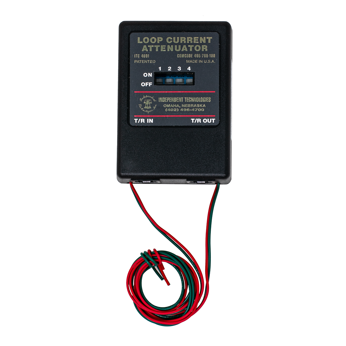
The Loop Current Attenuator has a set of four dip switches. You flip one at a time (in some combination) while watching the loop current come down to below 27ma on your meter (but above 23ma). At that point you just leave it, and it's fixed. You do need to buy one Attenuator per line that has high loop current. It will not reduce the volume level of the line, like resistors would. I've actually flipped the switches on the Loop Current Attenuator while watching a thousand cycle tone from the CO, and the audio level actually went up a hair all the way down to 20ma...That's pretty amazing! Don't mistake the Loop Current Attenuator for an audio attenuator (pad). Audio Attenuators are used to reduce the audio level of a line (dB) along with the DC loop current, usually by a fixed amount printed on the device, when the audio level of the line is too high. I'll talk more about Audio Attenuators in a little bit.
Most phone guys don't like playing with resistors, but if you'd like to try, here's what you've got to do - and it will work in some cases. As an example, many phone systems will get a squeal when two lines on the system are conferenced together if there is high loop current (and sometimes a loud line). Many years ago, TIE suggested replacing the bridging clips with 100-ohm (or whatever works) resistors to cure the squeal problem. It worked like a charm on every system I've tried it on, and I just used Radio Shack 100-ohm 1/2-watt resistors in all cases (1 watt resistors would be safer).
I figured that putting resistors in-series with the line couldn't help the volume of the line, so I tested it with a phone at the KSU by listening to the thousand cycle tone and using alligator clips to jump out the resistors. I couldn't notice a big drop, so I figured it was OK. In some cases of high loop current, the audio level is already high, like -4db, so you have some room to fool with resistors before the line isn't loud enough. If you're already at a -6 or -7db, you really don't have any room to play with the audio, and you should probably go right for the Loop Current Regulator which has some electronics to keep the level up.
At the time, I wasn't smart enough to think about what I was doing, or why I was doing it (lowering the loop current), so I didn't draw the correlation between that problem and others that I was having. I could kick myself now!
A PRIMER ON TELEPHONE LINE AUDIO LEVEL (dB)
One of the more common complaints that a telephone man hears is "Can't Hear". It may have been on only one call to Zanzibar, but here I am on a service call, and I've got to talk nicely to the customer. One of the problems with this service call is that I'm usually pretty powerless to do anything about it anyway, but I can't tell that to the customer.
Here's a little information that will let you actually do some testing if you think there really is a problem. Since you talk on your Butt-set all day, you probably have a good enough ear to be able to tell if a line isn't as loud as it should be. The ideal level for a telephone line loop loss seems to be about -5.5db. Local calls aren't too loud, and you can still hear OK on intercity and long-distance calls, which have a lot of loss compared to local calls.
The farther you get from the Central Office, the lower the volume is going to be on a call.
The first thing you need is a dB meter. Either use one designed for telephone lines, in which case an analog one is OK, or get a digital unit. The impedance of the line, be it 600-ohms or 900-ohms seems to make a difference to some extent. Telephone Circuit Loss Testers are made for this use, but I've found that even the Radio Shack digital meters that have a dB scale are OK, especially if you compare it to a "real" meter to get an idea of what kind of a difference in readings you will see. Once you use it on a few jobs, you'll get a feel for what you're looking at.
When you are measuring the dB loss of a line, you're reading only the AC component - the audio - of the phone line. At the same time, there is the DC talk battery component of the phone line of about 48VDC. Of all measurements, the DC voltage seems to be the one that you really shouldn't worry about (the voltage will follow the current... according to Ohm's Law). As I stated earlier, you connect a meter in parallel (across) with the telephone line to read dB. When you're trying to attenuate loop current by using resistors only, it's imperative that you have two meters, a meter to read the loop current and a meter to read the resistors' effect on the dB loss, so you know whether it's gone too low to be usable (anything below -7.5 dB would be hard to hear). You could use the same meter by changing the lead configuration and range, but that gets time consuming and frustrating. Since loop current measurements are not usually exactly the same line to line, you should repeat the process for each line. If you assume anything (like the loop current or circuit loss is the same on all the lines), it'll come back and get you!
The ideal dB loss to look for is -5.5dB, when calling the 1000 cycle test tone from the local CO. If you use the tone from another Central Office, you won't be able to tell the real loss on the line, since there is an additional (unknown) loss from CO to CO. I believe that the phone company is required to give you the correct phone number to use. In Chicago, there used to be a Test Line Coordinator who would give out these numbers all day long. They got rid of him, along with the Telephone Museum on Washington Street, years ago.
There are also numbers for silent termination, but CO specific silent termination numbers aren't important - you just want to have a nice quiet line to see if there is static or noise etc. on the local loop. They used to have ring back numbers here in Chicago, but they've done away with them years ago (they sure were handy for checking ringing!). That same ringback number had a couple of other neat features... it would beep once if you dialed the touchtone numbers correctly from 1 to 0,*,#, and had a rotary dial speed test built in. These features aren't very important today since electronic dials seldom go off frequency.
To see the effects of using the wrong test tone, dial up the test tone from a CO across the city. Then dial a test tone farther away, and then long distance to another city. I've been able to check the loss of various long-distance companies by calling the same test tone (like in New York), through AT&T (10288), MCI (10222), Sprint (10333) etc. You usually get a couple of dB loss across town, and 5 or more dB loss long distance... which is fine as long as the line started at a -5.5db. If you start with a line at -8.5db, which is the minimum that the phone company has to provide on a "line", that extra 3db loss makes it very hard to hear long distance.
There are two classes of phone lines that you can order from the telco. If you need to bring up the volume of a real phone line, changing it to a trunk is about the only way to do it.
A "Line" must be maintained by the phone company at -8.5db or greater. A "Trunk" must be maintained at -5.5db or greater (a lot louder) and can be either loop or ground start. I've had the phone company switch over quite a few customers with lines that were below -7 or -8dB, to trunks. The phone company then re-engineers the lines (adding loading coils or whatever) to bring it up to -5.5db. That 2 dB can really make a difference if you talk primarily long distance.
Amplified handsets and headsets help, but the increased gain from the amplifier also amplifies line noise, so it's often still hard to hear. A "Trunk" is usually a few bucks more per month than a "Line", plus the ordering and installation charge if you are having it changed from a "Line". They will always install new (conditioned) pairs from the CO when changing a line to a trunk.
Guys have asked if there's anything they can put on a line to bring the volume up if it's too low. Unfortunately, there's a problem using an amplifier on a 2-wire full duplex telephone line. On a 2-wire line both transmit and receive are on the same pair, as opposed to a 4 wire circuit where transmit and receive are on their own separate pairs.
On a 2-wire circuit, the transmit and receive gets separated in the phone's network, where a hybrid transformer sends receive audio up to your ear (the handset receiver) and sends the transmitted audio back down the phone line to the other end (from the handset transmitter). The hybrid transformer is not 100% efficient, meaning it's can't totally separate the transmit from receive. Maybe it's 90% efficient, which means that 10% of the receive audio gets sent back down the line - basically "feedback." When you amplify the line, that feedback is also amplified, which ends up sounding like ringing, singing or a squealing on the line. Sometimes you just can't amplify a 2-wire line enough to make a customer happy, before it starts to squeal.
On a 4-wire circuit, the transmit and receive have their own pairs. That means you can amplify the transmit and receive separately. There's nothing in the circuit feeding back part of the audio, so there's no squealing. Turn up the gain as much as needed. All of the trunks between COs are four wire circuits (either analog or digital), so the audio levels are perfect on calls across the city, or across the country.
There can also be problems with a particular phone or system if the hybrid in it isn't designed properly. The less efficient it is, the less you can amplify the line without feedback, and the more echo you have when the phone or system is attached to a digital line (like VoIP).
The only 2 wire amplifier I'm aware of still on the market is the Wilcom SB21-K2 Turbo Amp (603-524-2622, around $280) . It's an unbelievable little line powered device, designed for installation by unskilled Phone Company installers. It's made to go into an NI (Network Interface). The biggest drawbacks are that it has no gain control, and limited gain (maybe 9db?). It sets its level automatically when you dial the local 1KC tone (at the CO that pair is connected to), then a quiet termination, and then flip a switch. Even without a manual volume control, you can set it for maximum gain by dialing a 1KC tone in some other city which fools it - but you may end up with a squeal/feedback if you do that.
You may also be able to find used 2 wire amplifiers, like the Reliance VFR-5050. I've used it a few times on OPXs, although it's time consuming to install. I don't think it's full duplex (it has voice switching). The VFR-5050 is on a small card, so you need to buy a card cage with a power supply. I think it works in those card cages that the Long-Distance companies installed for their packs (with 25 pair cables and all), so you might be able to use an abandoned card cage that's lying around (I'm not sure it works). A nice thing about using the correct card cage is that the line gets passed through automatically if the card is pulled, so you don't cut-off anyone if you remove the card (an option?).
THE VOLUME ON AN OPX (OFF PREMISE EXTENSION) IS TOO LOW
In the old days, you could get conditioned pairs from the phone company that would repeat the voltage, current and audio level on an OPX (Off Premise Extension) as far as you needed to go. It looks like those days are over.
Today, most phone companies will give you a dry pair (unconditioned) from the near end (where the PBX is) to the far end (where the phone or telephone equipment is). The far end may be a branch office, an off-site worker, an office, or plant, or even the boss' house.
Spending the money on the dry pair and having it be unusable because the volume is too low doesn't make sense. We already talked about how to increase loop current and ring voltage.
We also mentioned a 2-wire amplifier like the Reliance VFR-5050, which will work OK if you find one and have a card cage for it (single line or multi-line). The Turbo Amp won't work because it has no gain adjustment. It's made to go on a real phone line with access to a 1KC tone at the CO (I suppose if you have enough loop current to run the line powered Turbo Amp and put in our 1KC tone generator on a station at the PBX, you could probably make it work?).
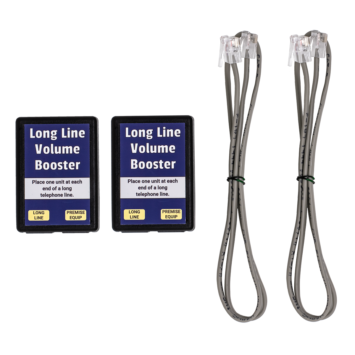
A better solution for an OPX is to use our Long Line Volume Booster™ Set. This is a pair of line powered devices. You need one on each end of the dry pair. It works like Load Coils, but you don't need to space them out along the pair. You just put one at each end of the line.
It will also work on a real phone line, but you'd need to be the phone company to use it because you'd need one at the CO or SLC, and one at the premise.
THE VOLUME ON CONFERENCE CALLS IS TOO LOW
Lots of guys ask if there's anything they can use to bring the volume up on lines that are conferenced on a phone system, so the outside parties can hear each other. Most phone systems don't have an amplified conference because it's expensive to put the parts in the system to do that.
When you simply bridge two lines together, which is what most phone systems do, you lose maybe 7dB (the circuit loss on the lines), between each of the outside parties. The person who created the conference in the middle (on the phone system), can hear the outside parties just fine. The two outside parties just can't hear each other. This is the case whether the trunks are conferenced together manually, or the phone system is performing an external call transfer, bridging (conferencing) one trunk to another to forward a call to another premise.
If you simply amplified each phone line the same amount in both directions, you'd get feedback, or the lines would sound too loud in one direction. The hard part about amplifying a conference call on 2 wire lines is that you only need to amplify the outgoing signal on each line - not both directions. Since an analog hybrid transformer used to separate transmit from receive isn't 100% efficient, you end up getting feedback and squealing when you try to amplify in one direction.
Although there are ways to amplify conference calls using sophisticated analog circuitry along with the most efficient hybrid transformers available, these days it's usually done with a DSP (Digital Signal Processor). The DSP is programmed to digitize the analog call, separate the transmit and receive digitally, digitally amplify the signal in one direction, and then convert the digital signals back to analog. Very few phone systems have amplified conferencing built-in, but that may change as DSPs (and programmers in India or wherever) get less expensive.
There's NOTHING that will work to increase the level of conferenced trunks on a phone system except a Conference Bridge. A Conference Bridge is a fairly expensive digital device (with DSPs to adjust the incoming and outgoing volume) that goes on analog station ports on a phone system. To create the conference, you dial into the conference bridge, and manually dial codes to setup or tear-down the conference. Because the DSPs in the conference bridge are programmed to bring the levels up to the correct levels, conferenced calls will sound great.
I personally ALWAYS order 3-Way Calling from the CO for my customers... and they LOVE IT! That heads off the complaints I'd invariably get when they try to make their first conference call using the phone system's conference feature. You just have to make sure you order 3-Way Calling from the phone company, and that you program a flash button on every phone. That's all it takes to have perfect conference calls. Why are they perfect? Because the amplification is applied as needed at the CO on 4 wire circuits, before the line is converted to 2 wire to go to the premise. No amplification has to be done on 2 wire circuits.
WHAT IF THE VOLUME ON A LINE IS TOO LOUD?
Touch tones and echo are two reasons that you may have to reduce the volume level of a line. Reducing the level is easier than amplifying it!
An Audio Attenuator will reduce the audio level on a line by a set amount, and also reduce the loop current by about 1ma for every 1db of attenuation. We make both Modular and 66 Block type Attenuators, in 1, 2, 3, 4, 6 and 8dB models. We also make a Modular Telephone Line Loss Insertion Tester #CID9I that will insert 1, 2, 4 or 4db of attenuation in-series with a modular device. If you add a fixed 4dB Attenuator in-series with the Tester, you can get 5, 6, 7 or 8dB of attenuation. Once you know how much attenuation you need on the lines using the Tester, you can order the correct fixed value Attenuators.
If you have DTMF recognition problems, or there's too much echo either on a trunk or analog station port on a digital system, or a system using VoIP lines, reducing the level of the line or port can fix or improve the symptoms. If the phone system doesn't have an option to reduce the level through programming, using physical Attenuators (or resistors) is the only way to get the level down.
Two other devices that may fix DTMF recognition and echo problems are our Half REN Box™ #CID9A , and our Echo Stopper™ Impedance Matcher #WAL5F .
Both of these devices change the impedance of the line at voice frequencies, which may help DTMF digits get recognized by a voice mail or IVR system, or reduce the echo on a phone line.
Just putting the Half REN Box™ on the line will tell you whether it fixes the problem. The Echo Stopper™ Impedance Matcher has a pot and button that needs to be tried to see if it fixes the problem. Since there aren't any meters that will tell you whether there's an impedance problem, the easiest way to see if that's your problem is to just change the impedance by putting these devices on the line.
Related Reading: